-40%
RTC Add-on Board, DS1307, 5V, I2C, IDC10 connector (RTC2 Board)
$ 4.35
- Description
- Size Guide
Description
RTC Add-on Board, DS1307, 5V, I2C, IDC10 connector (RTC2 Board)MIKROE-330
Real-Time Clock counts seconds, minutes, hours, date, month, day, and year with leap-year
Standard I2C interface
Programmable square-wave output signal
The RTC2 Board features the DS1307 serial real-time clock (RTC). It is a low-power, full binary-coded decimal (BCD) clock/calendar plus 56 bytes of NV SRAM. Timekeeping operation continues even when the power supply goes off as it is then powered from the backup supply. The RTC2 Board serves as an extension of existing development boards in applications where real-time data is required.
The board has a female IDC10 connector to plug it into a development system. It communicates with the host system via I2C. There two options for location of the SCL and SDA pins; their position can be changed by soldering an SMD jumper. By default it is on pins 4 and 5, compatible with the RC3 and RC4 pin locations on PIC development systems from mikroElektronika. Soldering the jumper will move them to pins 1 and 2, compatible with PC0 and PC1 pin locations on mikroElektronika's AVR development systems. SQW/OUT is on pin 3. VCC is pin 9. GND is pin 10.
Use in your own design
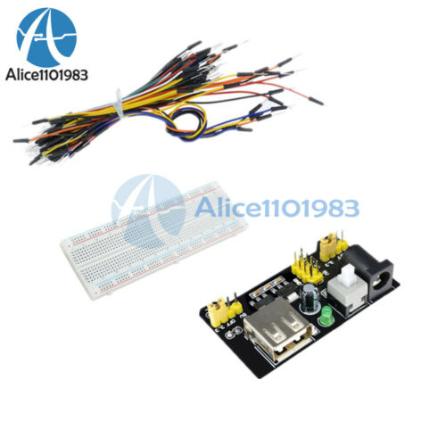
While this board was created originally for mikroElektronika's development systems, it's certainly possible to use in your own project. To do so, you may want to pick up
IDC10 box headers
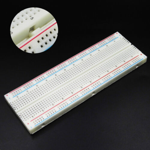
that you can solder onto your PCB, or an
EasyTEST
board and
jumper wires
to wire it up however you need to.
Note:
This board uses 5V power supply only. To add RTC to a 3.3V system, the
3.3V RTC Board
is available with a similar IDC10 interface.
RTC Add-on Board Resources
DS1307 RTC Add-on Board User Manual
RTC2 Board Example Code
in C, BASIC and Pascal for PIC, dsPIC, AVR and 8051, e.g.
mikroC-PIC
,
mikroC-dsPIC
,
mikroC-AVR
,
mikroC-8051
Maxim DS1307 Page
with datasheet and other documentation

